
Setting Up Your ESP8266 IoT Sensor Timer Easily
Originally posted on January 26, 2024 @ 8:55 pm
We are pleased to introduce you to our tutorial for configuring your ESP8266 IoT sensor timer. This flexible device enables you to automate tasks and gather information in your smart home. It has the ability to control lighting, track temperature and humidity, and schedule appliances. With the ESP8266 IoT sensor timer, the possibilities are endless.
In this article, we will walk you through the process of setting up your ESP8266 IoT sensor timer easily. We will cover everything from the necessary components to the assembly of the PC board. By the end of this guide, you’ll have your ESP8266 IoT sensor timer up and running, ready to make your life more convenient and efficient.
So, let’s get started and dive into the world of ESP8266 IoT sensor timers!
Key Takeaways
- The ESP8266 IoT sensor timer is a versatile device that automates tasks and collects data in your smart home.
- Setting up your ESP8266 IoT sensor timer is a straightforward process with the right components and guidelines.
- The design of the ESP8266-01 module and power supply options play an important role in the functionality of your IoT sensor timer.
- Assembling the PC board requires soldering and careful attention to detail to prevent short circuits.
- Testing and programming the ESP8266-01 module is essential to ensure its proper functionality.
The Design of the ESP8266-01 Module
The design of the ESP8266-01 module plays a significant role in determining its functionality as an IoT sensor timer. Understanding the module’s GPIO pins is essential for utilizing its capabilities effectively.
The ESP8266-01 module features several GPIO pins, including GPIO0, GPIO2, TX, and RX. While these pins offer versatility, not all of them can be used as digital outputs due to their power-up modes.
For driving an output relay, the RX pin is the most suitable choice as it is set as an input during power-up. However, it’s crucial to pull certain pins high using resistors to ensure the correct boot-up mode. This ensures the module functions as intended, providing reliable performance for your IoT projects.
Additionally, the ESP8266-01 module includes a MODE/SET button connected to GPIO2 and an indication LED connected to GPIO0. These features enhance the usability and functionality of the module, allowing for convenient configuration and visual cues.

ESP8266-01 Module GPIO Pins
| GPIO Pin | Function |
|---|---|
| GPIO0 | Indication LED |
| GPIO2 | MODE/SET Button |
| TX | Serial Transmit |
| RX | Input for Driving Output Relay |
The GPIO pins of the ESP8266-01 module provide the necessary interfaces to build and control your IoT sensor timer. Understanding their functionalities enables you to utilize them effectively and unlock the full potential of your ESP8266-01 module.
Power Supply Options
The ESP8266 IoT sensor timer offers versatile power supply options to meet your specific requirements. You can choose between two main options:
- 12-24V DC
- 220V AC
For the 12-24V DC option, a reliable DC-DC converter is used to provide a regulated 5V output. This ensures a stable power supply for the ESP8266-01 module. Additionally, the 3.3V rail, which is necessary for the proper functioning of the module, is obtained from a linear regulator powered by the 5V rail.
To guarantee the smooth operation of the power supply, both the 5V and 3.3V rails are equipped with noise filtering capacitors. These capacitors effectively suppress voltage ripple and high-frequency interference, providing clean and steady power to the ESP8266-01 module.
On the other hand, if you prefer the 220V AC option, a compact 220V/5V switch mode power supply is employed. This power supply option offers convenience and simplicity, effectively converting the mains AC voltage to a stable 5V output.
Noise Filtering Capacitors
One key component in the power supply setup for the ESP8266 IoT sensor timer is the noise filtering capacitor. This capacitor is responsible for reducing voltage ripples and filtering out high-frequency interference. By effectively suppressing these unwanted electrical fluctuations, the noise filtering capacitors ensure a reliable and stable power source for the ESP8266-01 module.
“The noise filtering capacitors play a vital role in maintaining a clean and uninterrupted power supply to the ESP8266 IoT sensor timer.”
| Noise Filtering Capacitors | Description |
|---|---|
| 5V Rail Capacitor | A high-quality capacitor with the appropriate capacitance and voltage rating is used to filter the 5V rail, providing a smooth power supply to the ESP8266-01 module. |
| 3.3V Rail Capacitor | To ensure the stability of the 3.3V rail, a dedicated capacitor is employed. This capacitor filters out any residual noise present in the power supply, enabling the reliable operation of the ESP8266-01 module. |
By incorporating noise filtering capacitors into the power supply design, any potential disturbances that could affect the performance of the ESP8266 IoT sensor timer are effectively mitigated. This ensures accurate data collection and seamless automation in your smart home setup.

With these power supply options and noise filtering measures in place, you can confidently set up your ESP8266 IoT sensor timer knowing that it will receive reliable and clean power to perform its tasks seamlessly.
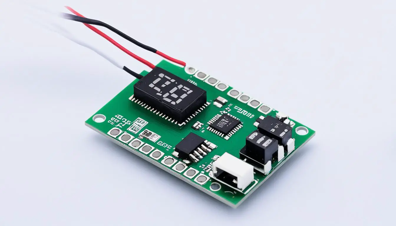
Assembling the PC Board
When it comes to building your ESP8266 IoT sensor timer, assembling the PC board is a crucial step. This section will guide you through the process of assembling the board using the Eagle software and soldering the necessary components to ensure a well-functioning device.
Designing the PC Board with Eagle Software
To begin the assembly process, we utilize the powerful Eagle software to design the PC board. This software allows for easy customization and ensures the correct placement of components on the board. By following the schematic diagram and layout guidelines, you can create a single-sided board tailored to your specific needs.
Eagle software provides an intuitive interface and extensive library of components, making it an ideal choice for designing your ESP8266 IoT sensor timer PC board.
Soldering Components for Optimal Performance
Once your PC board design is complete, it’s time to gather the necessary components and start soldering. Here’s a list of the key components you’ll need to assemble:
- ASM1117 regulator
- Resistors
- Diodes
- Headers
- Screw terminals
- Relay
- Transistor
- Capacitor
Take care to solder each component accurately and securely, ensuring no short circuits between pads. Precision is key to avoid any potential disruptions in device performance.

Handling Large Currents with Proper Soldering
One critical aspect of assembling the PC board for your ESP8266 IoT sensor timer is soldering the tracks between the relay contacts and screw terminals. It is essential to apply a sufficient amount of solder to these tracks to ensure they can handle large currents reliably.
By dedicating attention to this specific step, you can ensure the longevity and stability of your device, even when dealing with high-power applications.
| Component | Quantity | Specification |
|---|---|---|
| ASM1117 regulator | 1 | 5V voltage regulator |
| Resistors | Varies | Various resistance values |
| Diodes | 2 | General-purpose diodes |
| Headers | 2 | Pin headers for connectivity |
| Screw terminals | 2 | Terminal blocks for easy connections |
| Relay | 1 | Electromechanical relay |
| Transistor | 1 | NPN transistor |
| Capacitor | 2 | Various capacitance values |
By following these steps and paying attention to detail during the assembly process, you’ll have a well-assembled PC board ready for the next steps in building your ESP8266 IoT sensor timer.
Testing and Programming the ESP8266-01 Module
Before we begin testing and programming the ESP8266-01 module, it’s important to follow a few crucial steps to avoid any potential issues. First, we need to remove the module from the circuit to prevent it from overheating the regulator. Now, let’s dive into the testing and programming process.
One of the simplest ways to test the functionality of the ESP8266-01 module is by using the Arduino IDE. It provides a user-friendly platform for programming the module and executing various tasks. To get started, connect your ESP8266-01 module to your computer using a USB-to-UART converter.
Note: If you’re new to programming the ESP8266-01 module, there are a few essential tools and libraries you’ll need. Make sure you have the latest version of the Arduino IDE installed, along with the ESP8266 core library.
Now, let’s run a simple timer example to test the module’s functionality. You can easily find timer examples in the Arduino IDE’s library or online resources. These examples utilize the os_timer function to generate interrupts at specific intervals, allowing precise control over timing operations.
When working with interrupts on the ESP8266-01 module, it’s important to keep the Interrupt Service Routine (ISR) short and efficient. Avoid using serial print commands within the ISR, as it may disrupt the timing and cause unexpected behavior. Instead, consider using other methods to debug your code, such as blinking LEDs or sending data wirelessly to another device.
Note: To ensure accurate timing and prevent conflicts, it’s recommended to disable interrupts within the ISR and use
yield()ordelay(0)in the main loop. These functions allow the underlying operating system to perform its tasks effectively.
With the timer example successfully running on your ESP8266-01 module, you can further explore the capabilities of the Arduino IDE and the ESP8266 ecosystem. Take advantage of the vast library of pre-built functions, experiment with different timers and interrupts, and unleash the full potential of your ESP8266-01 module for your projects.
ESP8266-01 Module Testing and Programming Tips:
- Disconnect the ESP8266-01 module from the circuit before applying power to avoid overheating the regulator.
- Ensure you have the latest version of the Arduino IDE and the ESP8266 core library installed for seamless programming.
- Keep the Interrupt Service Routine (ISR) short and efficient, avoiding serial print commands within the ISR.
- Disable interrupts within the ISR and use
yield()ordelay(0)in the main loop for accurate timing.
By following these tips and experimenting with different functions and examples, you’ll be able to harness the full potential of the ESP8266-01 module for your projects.
This image showcases the ESP8266-01 module being tested and programmed using the Arduino IDE. As you can see, the development environment provides a user-friendly interface for writing and uploading code to the module.
Conclusion
The ESP8266 IoT sensor timer is the perfect DIY project for anyone looking to enhance the automation and data collection capabilities of their smart home. By following the steps outlined in this article, you can easily set up your own ESP8266 IoT sensor timer with little effort. This device allows you to customize and control various tasks in your home, making it truly smart and efficient.
With the ESP8266 IoT sensor timer, you can automate lights, appliances, and other systems based on time schedules or specific triggers. This level of automation not only adds convenience to your daily life but also helps you save energy and reduce your ecological footprint. Imagine coming home to a house that automatically adjusts the temperature, turns on the lights, and brews a fresh cup of coffee – all just the way you like it.
Furthermore, the data collection capabilities of the ESP8266 IoT sensor timer enable you to gather valuable insights about your home and its environment. You can monitor temperature, humidity, air quality, and more, all from your smartphone or computer. Having this data at your fingertips allows you to make informed decisions about energy usage, ventilation, and overall comfort in your smart home.
So why wait? Start your ESP8266 IoT sensor timer project today and unlock the full potential of your smart home. With just a few simple steps, you can create a customized automation system that not only saves you time and energy but also provides valuable data for better decision-making. Embrace the power of the ESP8266 IoT sensor timer and transform your home into a truly smart and connected space.
FAQ
What is an ESP8266 IoT sensor timer?
The ESP8266 IoT sensor timer is a versatile device that allows you to automate tasks and collect data in your smart home. It is designed to easily integrate into your home automation system and enhance its functionality.
What are the important components of the ESP8266-01 module?
The ESP8266-01 module has several GPIO pins, including GPIO0, GPIO2, TX, and RX. The RX pin is the most suitable for driving an output relay. It also has a MODE/SET button connected to GPIO2 and an indication LED connected to GPIO0.
How can I power the ESP8266 IoT sensor timer?
You can power the ESP8266 IoT sensor timer using two options. The first option is to use a 12-24V DC power supply and a DC-DC converter to provide a regulated 5V output. The second option is to use a small 220V/5V switch mode power supply if you prefer using AC power.
How do I assemble the PC board for the ESP8266 IoT sensor timer?
The PC board for the ESP8266 IoT sensor timer can be easily made at home using the Eagle software. The assembly process involves soldering components such as the ASM1117 regulator, resistors, diodes, headers, screw terminals, relay, transistor, and capacitor. Ensure proper soldering and avoid short circuits between pads.
How do I test and program the ESP8266-01 module?
To test the functionality of the ESP8266-01 module, you can use a simple timer example in the Arduino IDE. The example utilizes the os_timer function to generate interrupts at specific intervals. Remember to keep the ISR short, avoid using serial print commands within the ISR, and disable interrupts in the ISR. Use yield() or delay(0) in the main loop to allow the underlying operating system to perform tasks.
What are the advantages of using an ESP8266 IoT sensor timer in my smart home?
The ESP8266 IoT sensor timer provides an easy and efficient way to automate tasks and collect data in your smart home. By setting up your own ESP8266 IoT sensor timer, you can customize your home automation system and collect precise data for various purposes.